
Cement
Engineered valve solutions tailored for critical Cement operating processes.

The Hydraulic Float Control Valve is designed to automatically regulate water levels in storage tanks and reservoirs without requiring external electrical power. It uses a hydraulic float pilot mechanism to control the main valve according to the tank water level. As the water reaches the preset maximum level, the pilot mechanism controls the valve to restrict or stop the incoming flow, helping prevent overflow. It is suitable for water treatment plants, water distribution networks, reservoirs, pumping stations and industrial water storage systems.
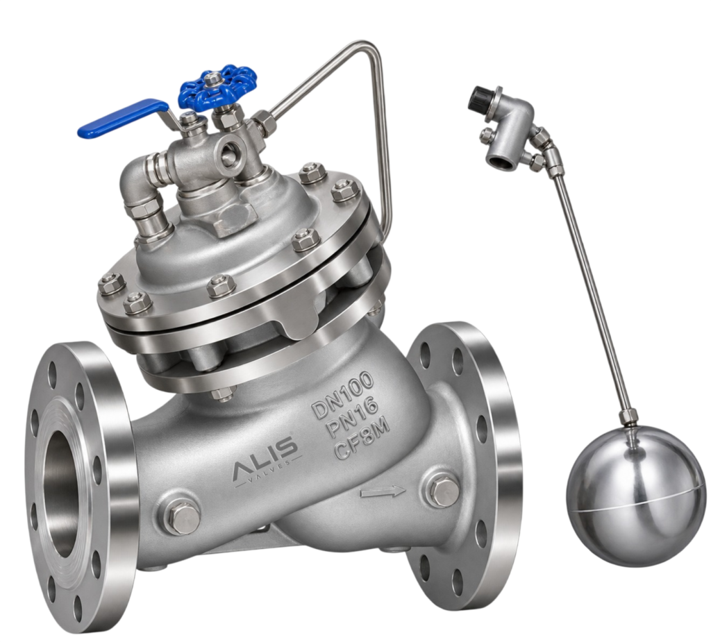
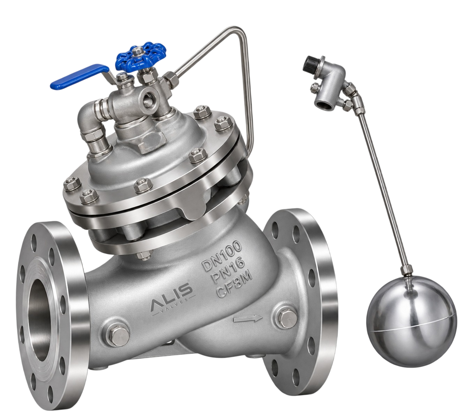
The Hydraulic Float Control Valve is an automatic water-level control valve designed to maintain the required water level in storage tanks, reservoirs and water distribution systems. It operates through a hydraulic pilot mechanism that senses changes in water level and controls the opening or closing of the main valve.
Unlike electrically operated level-control systems, a hydraulic float control valve can operate through water pressure and mechanical float movement, without requiring an external electrical power supply for its basic level-control function.
Construction and Working Principle
A typical hydraulic float control valve assembly consists of a main valve body, diaphragm or piston operating mechanism, pilot control system, float assembly, connecting tubing and internal flow-control components. The exact construction depends on the selected valve design.
The float is installed in the storage tank and connected to the pilot mechanism through a suitable hydraulic or mechanical arrangement.
When the water level falls below the preset level, the float mechanism changes the pilot valve position, allowing the main valve to open or increase its opening. This permits water to enter the tank.
As the water level rises and reaches the preset maximum level, the float moves to its upper position and operates the pilot mechanism. The pilot controls the hydraulic pressure acting on the main valve actuator, causing the main valve to close or reduce incoming flow, depending on the valve design.
This automatic operation helps maintain the required tank level and reduces the risk of water overflow.
Key Design Features
Automatic water-level regulation.
Hydraulic pilot-operated control mechanism.
Float-based level sensing.
No external electrical power required for basic hydraulic operation.
Helps prevent tank and reservoir overflow.
Suitable for selected water storage and distribution applications.
Available in different sizes, materials and pressure ratings depending on design.
Can be configured for different level-control requirements.
Size Range
DN50–DN300 (2"–12"), indicative
Pressure Rating
PN10 / PN16 / PN25 Subject to model
Cover Material
Ductile Iron / Cast Iron
Body Material
Ductile Iron / Cast Iron
Diaphragm Material
EPDM / NBR
Internal Trim
Stainless Steel
Temperature Range
0°C to 80°C, indicative
Flow Direction
As Marked on Valve
Power Supply
No External Electrical Supply
Pilot Type
Hydraulic Float Pilot
Engineered valve solutions tailored for critical Cement operating processes.
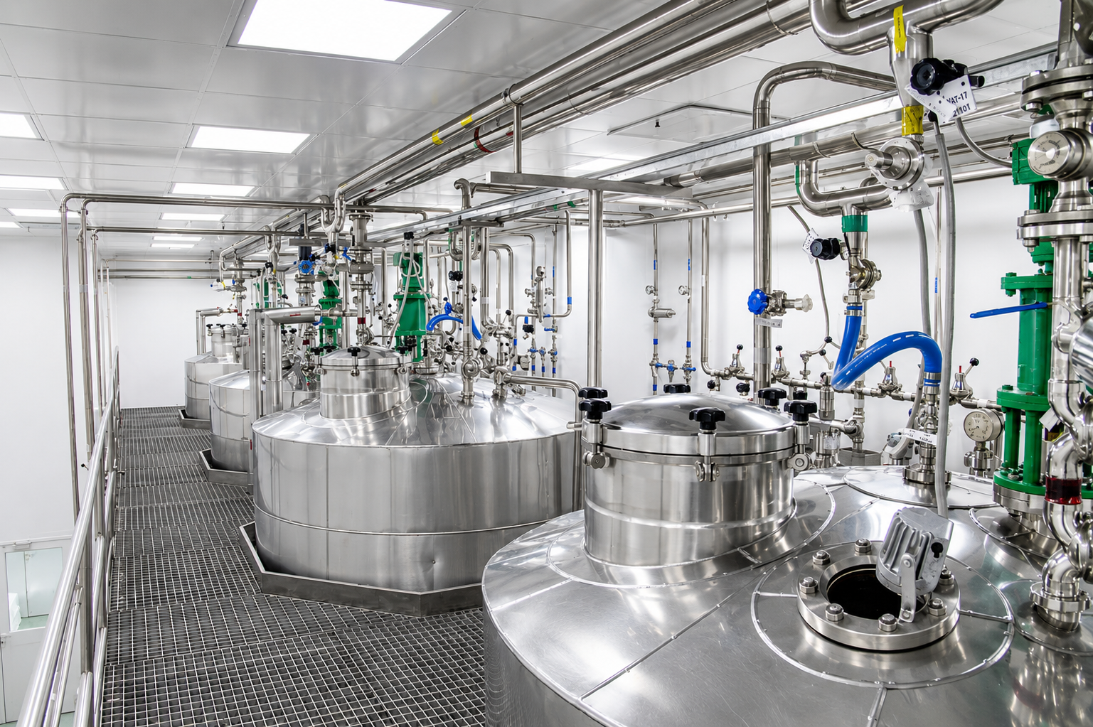
Engineered valve solutions tailored for critical Chemical operating processes.

Engineered valve solutions tailored for critical Data centres operating processes.

Engineered valve solutions tailored for critical Fertilizer operating processes.
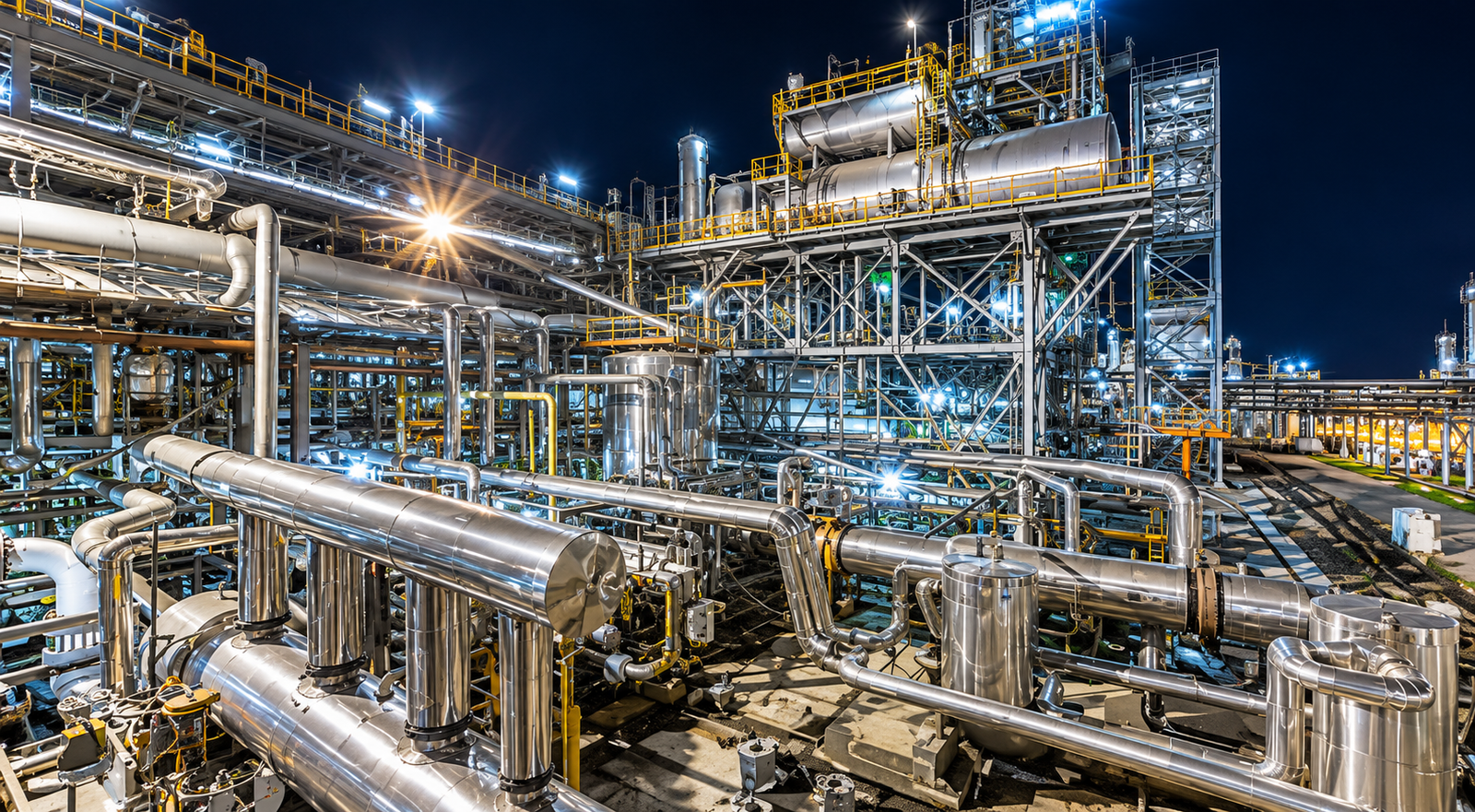
High-performance flow automation engineered for Ammonia operations.
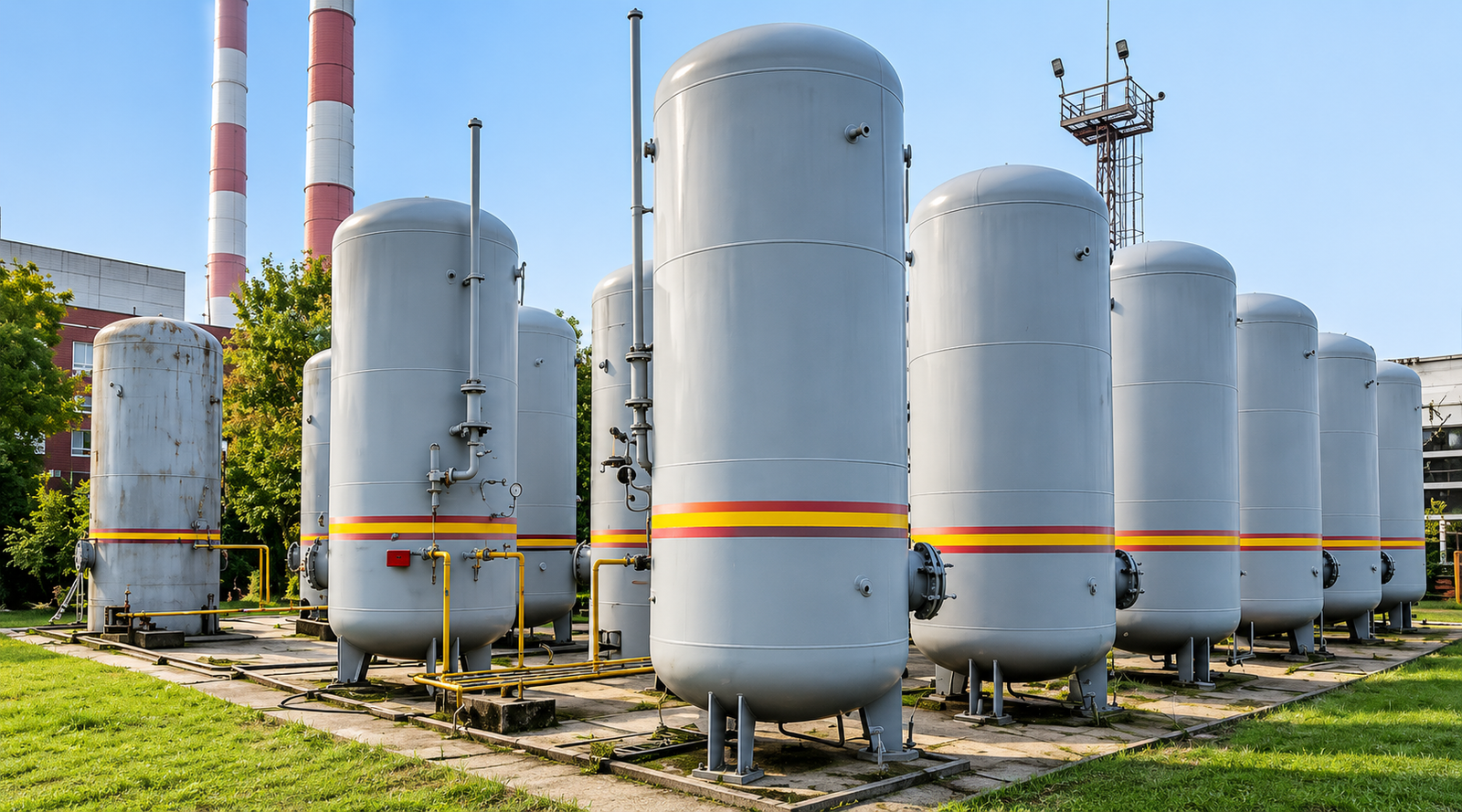
High-performance flow automation engineered for CO₂ operations.
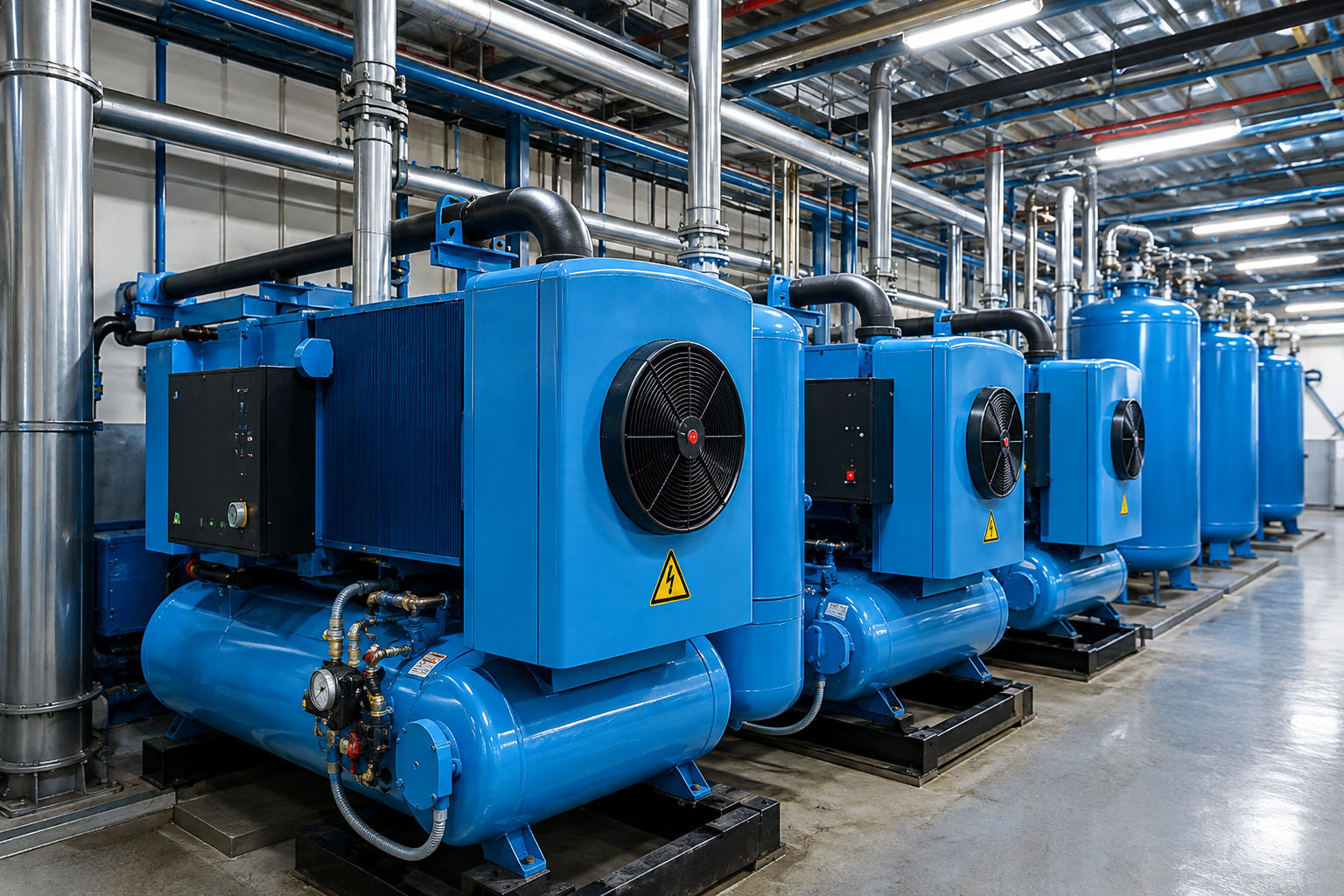
High-performance flow automation engineered for Compressed Air operations.
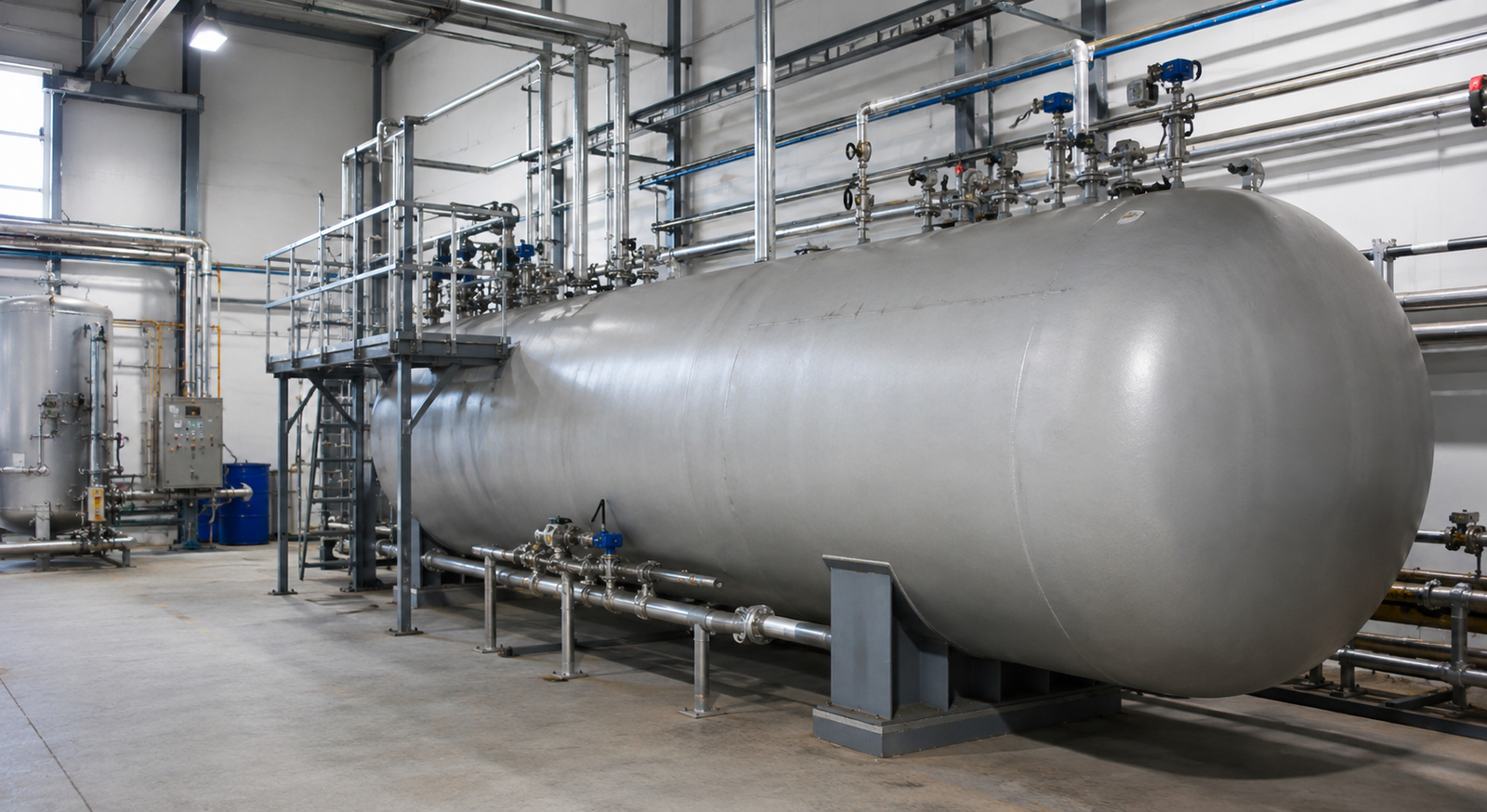
High-performance flow automation engineered for Cryogenic operations.
Hydraulic Float Control Valve Product Brochure
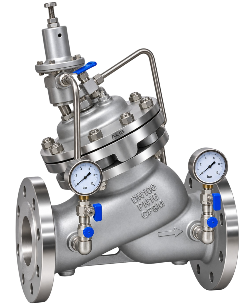
ALIS Valves is a Diaphragm Type Pressure Stabilizing Valve Manufacturer India, offering…
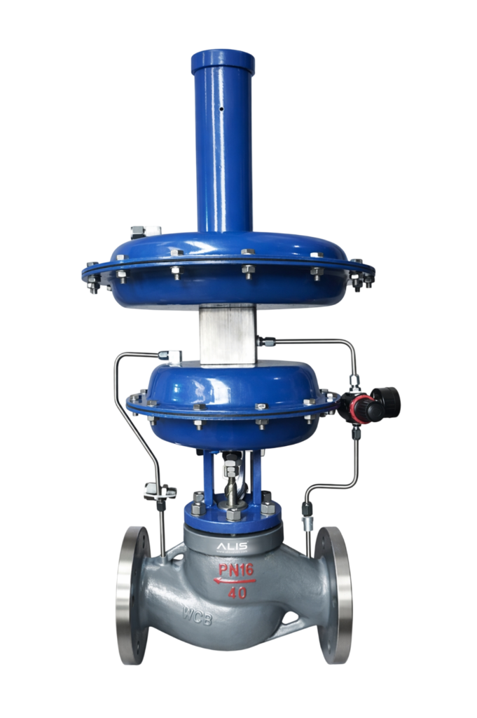
ALIS Valves is a leading Pneumatic Diaphragm Globe Control Valve Manufacturer &…

ALIS Valves is a Pneumatic Sanitary Diaphragm Valve Manufacturer in India, offering…
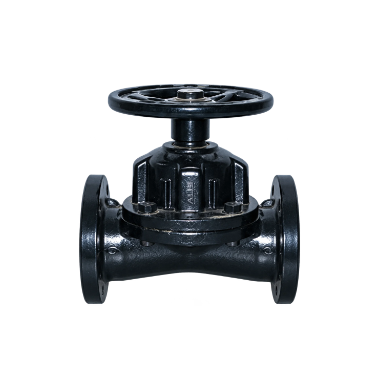
Rubber Lined Diaphragm Valve Manufacturer in India is designed for reliable flow…