
Cement
Engineered valve solutions tailored for critical Cement operating processes.

The Manual Lug Type Butterfly Valve is designed for reliable on/off flow control in industrial piping systems. As a Manual Lug Type Butterfly Valve Manufacturer in India, ALIS Valves offers valve solutions for industrial applications requiring dependable flow isolation. Its lug-style body allows bolted connections to matching pipeline flanges and can support end-of-line service when specifically rated for that purpose. Operated by a manual lever or gearbox, the Industrial Lug Type Butterfly Valve is commonly used in water treatment, HVAC, chemical processing and general industrial applications.
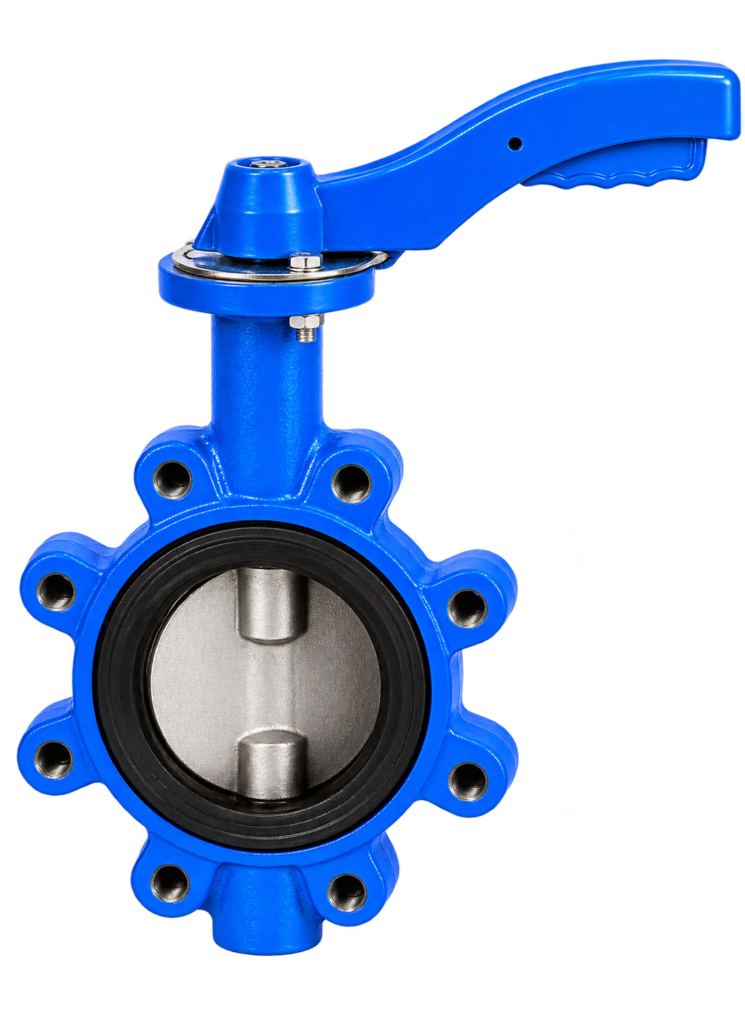
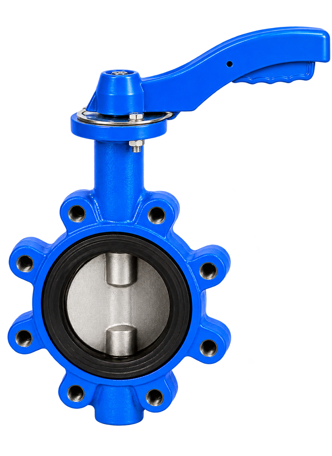
A Manual Lug Type Butterfly Valve controls fluid flow through a pipeline using a rotating disc mounted on a central shaft. Turning the handle or gearbox through approximately 90 degrees opens or closes the valve, providing straightforward manual operation without requiring electricity or compressed air.
The valve body features threaded lugs around its circumference. These lugs allow the valve to be bolted between compatible pipeline flanges. Depending on the valve design and pressure rating, the lug construction may also allow one side of the pipeline to be disconnected while the valve remains secured to the other side.
Manual lug type butterfly valves are used in water distribution, wastewater treatment, cooling systems, HVAC, manufacturing and compatible process applications. The appropriate body material, disc material, seat material and pressure rating should be selected according to the fluid, operating temperature and pipeline requirements.
Size Range
2″–24″ (DN 50–DN 600), indicative
Body Material
Cast Iron / Ductile Iron / Carbon Steel / Stainless Steel, depending on model
Disc Material
Ductile Iron / Stainless Steel / Coated Disc, as available
Seat Material
EPDM / NBR / PTFE, depending on design
Pressure Rating
PN 10 / PN 16, depending on model
Temperature Range
Depends on seat, materials and pressure
Indicative Temperature Range
−20°C to 120°C for selected configurations; verify datasheet
Engineered valve solutions tailored for critical Cement operating processes.
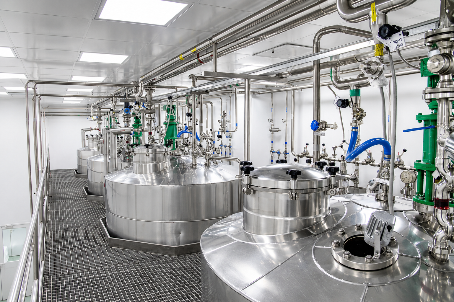
Engineered valve solutions tailored for critical Chemical operating processes.

Engineered valve solutions tailored for critical Data centres operating processes.

Engineered valve solutions tailored for critical Fertilizer operating processes.

Industrial Valves for Ammonia Applications Industrial valves used in ammonia systems are selected according…
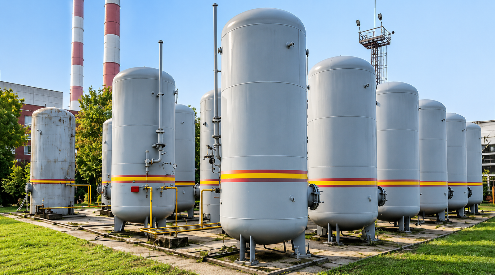
High-performance flow automation engineered for CO₂ operations.
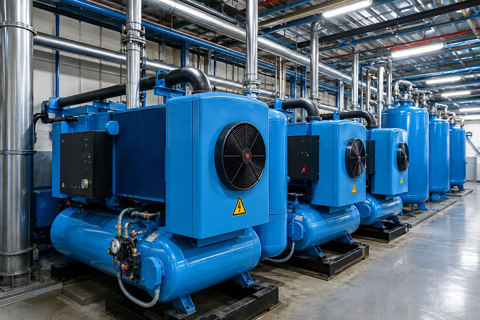
High-performance flow automation engineered for Compressed Air operations.
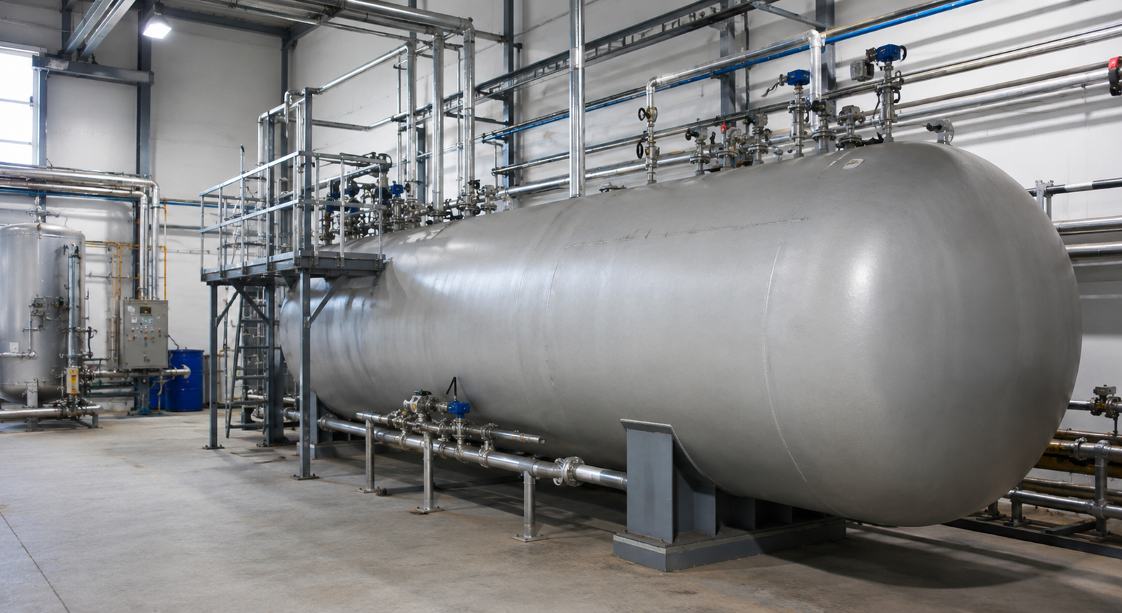
High-performance flow automation engineered for Cryogenic operations.
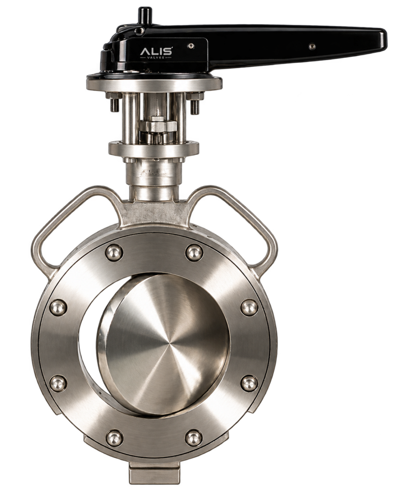
Alis Valves is Spherical Disc Butterfly Valve Manufacturer in India is designed…
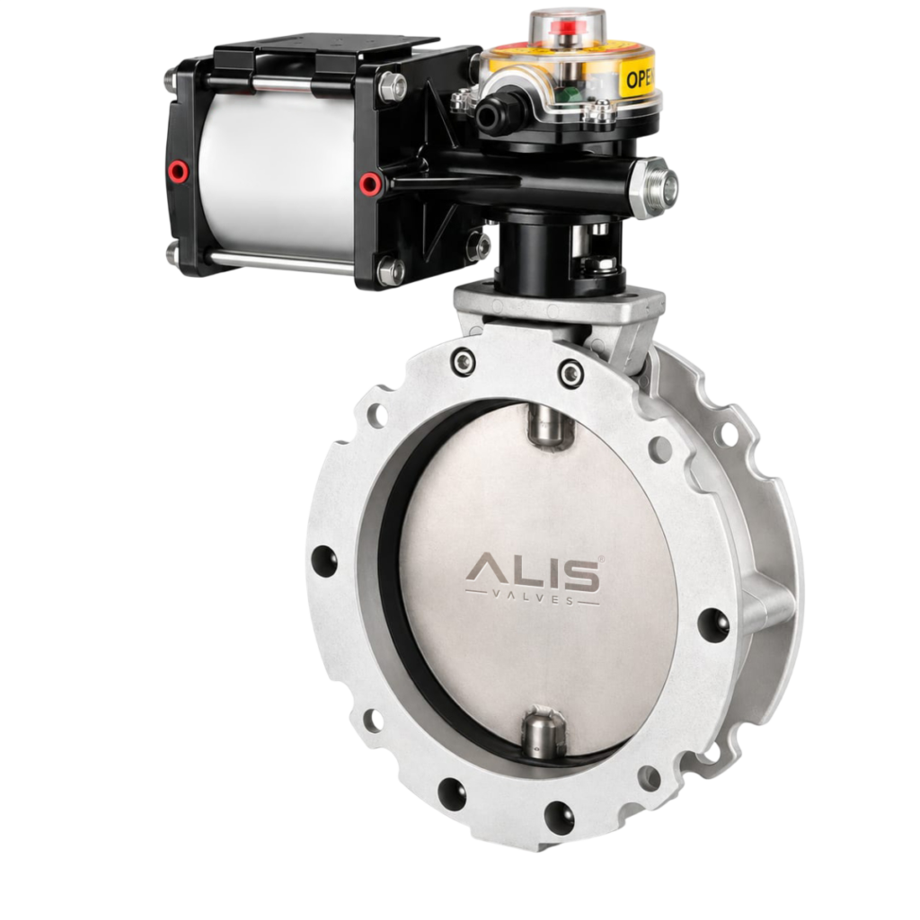
Aluminium Cement Butterfly Valve Manufacturer Supplier India is designed for reliable isolation and…
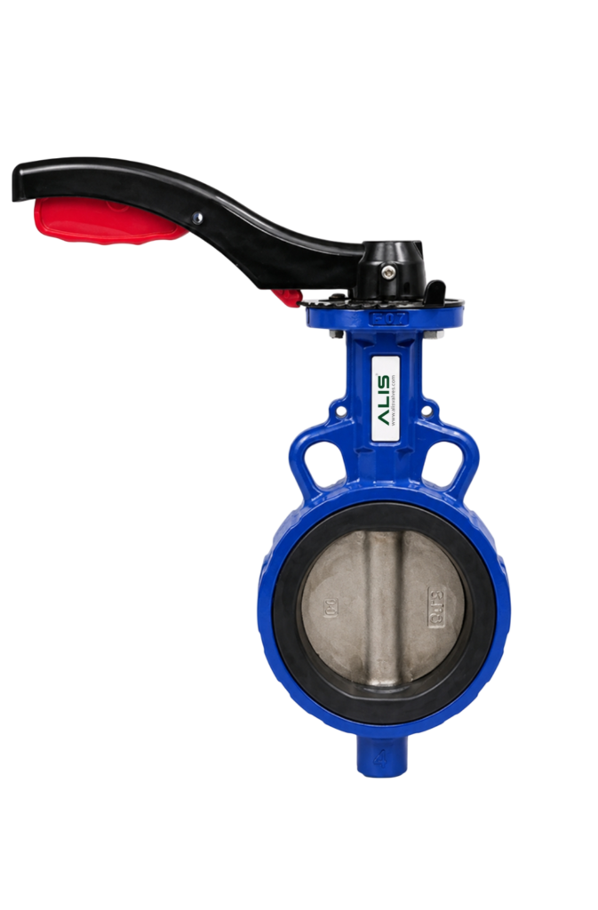
ALIS Valves is a leading Manual Wafer Type Butterfly Valve Manufacturer in…
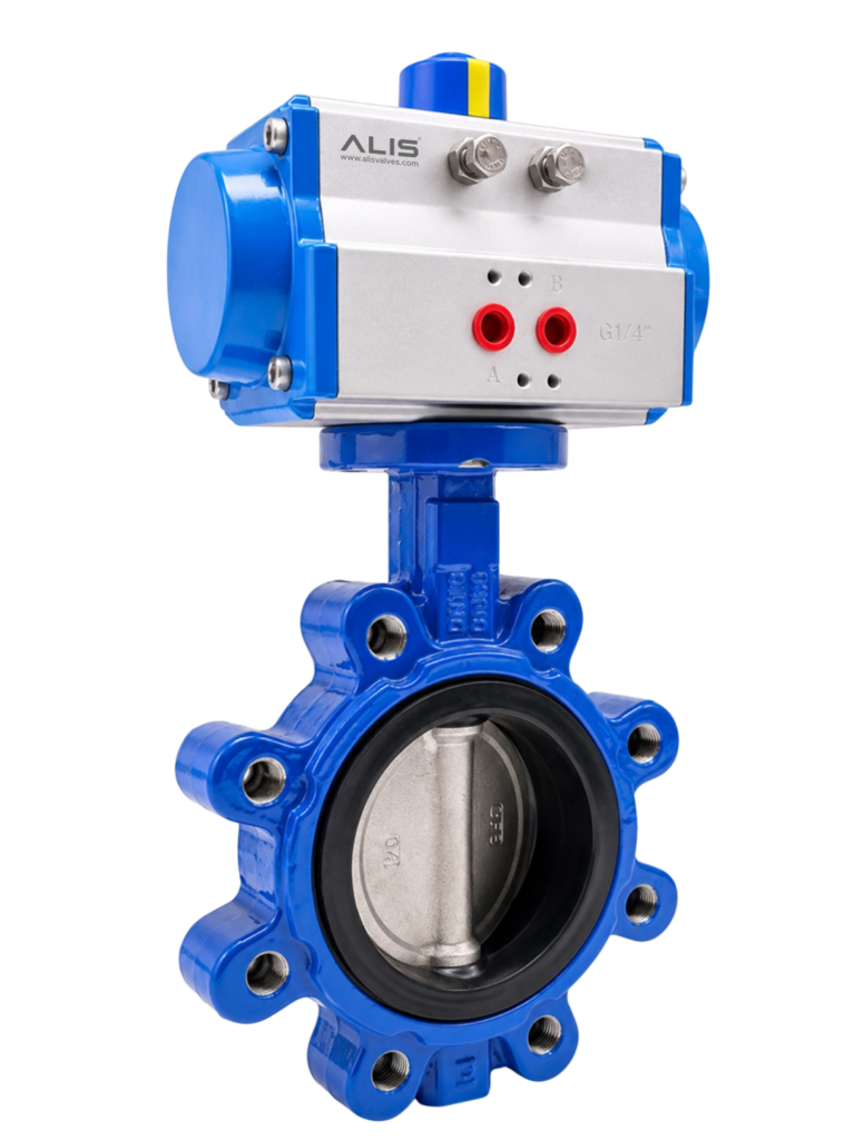
ALIS Valves is a leading Pneumatic Lug Butterfly Valve Manufacturer in India,…